Prevention and Mitigation Measures
April 15, 2021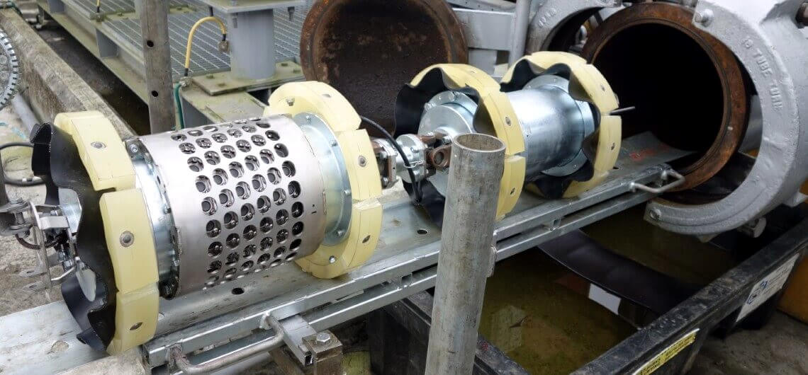
At Integrity EPC, we understand how valuable an operators’ time is. In-line inspection can be a very time consuming project with many components, which is why we can came up with a streamlined process to make sure everything is evaluated and accounted for. Below is a look into our process:
- Assess the pipeline to determine if it can be adequately inspected and make modifications if necessary (consult with ILI vendor)
- Launch traps – Should have an overbore of sufficient length to take the complete length of the inspection tool plus 1D. Sufficient access area will be required to accommodate the pig and the ILI vendor’s equipment.
- Receive traps – Nominal bore should be longer than the trailing modules of the ILI tool. Overbore should be the length of the first module plus 3 ft. The kicker line should be close to the reducer (not close to the door). Sufficient access area will be required to accommodate the pig and the ILI vendor’s equipment.
- Bends – Most tools can pass through 1.5D bends, but certain MFL tools for thick walls can only pass 3D bends. Miter or lobster back bends greater than 15 degrees are usually unacceptable for ILI tool passage. Back-to-back bends may cause problems with some tools; the ILI vendor should be consulted.
- Tees – Where the branch exceeds 50% of the main pipeline diameter, bars should be fitted. If the tee is not at 90° to the mainline, pig bars should be fitted and an investigation should be carried out to ensure that the distance between the drive cups on the tool is greater than the opening to the tee.
- Line – Constant nominal size (single diameter). Inform the ILI vendor if thick wall is anticipated (in case a special tool is required). A listing of the various wall thicknesses on the line by location should be prepared and delivered to the ILI vendor for review.
- Valves – Must be full bore. Gate valves must not leave a cavity when the gate is withdrawn (the cavity can cause the pig to jam and become lodged).
- Flow conditions – Velocities of the product must be below the maximum acceptable tool velocity for the full length of the pipeline to avoid loss of data. Large elevation changes can cause slack line problems. A description of flow rates and operating pressures to be encountered during the tool run should be sent to the ILI vendor.
- Request for quotes from various ILI vendors – A Pipeline Questionnaire is typically required.
- Select ILI vendor and set contract requirements and scheduling – Include specification for a successful run, responsibility for a re-run, responsibility for a stuck pig, etc.
- Cleaning the pipeline – Select pigs based on historical knowledge of the line or previous experience. If no historical knowledge it is often an iterative procedure – starting with foam pigs and progressively get more aggressive (disk, brush, scraper, etc.).
- A gauge pig is run after cleaning is completed to the ILI vendor’s satisfaction to ensure the pipeline ID is acceptable for caliper or combo (caliper and MFL) tool passage.
- Smart tool(s) is run – AGMs are also placed along the pipeline approximately every mile and tracked by either company or contractor personnel to ensure the tool is moving through the pipeline without any issues. Coordinate values for each AGM placement must be listed.
- After receiving the tool(s), the data is checked by the contractor to ensure the tool functioned properly and a successful inspection was completed (typically confirmed within 24 hours of receiving the tool).
- A preliminary report shall be issued to the integrity engineer/client within 2-3 weeks of receiving the ILI tool so that verification digs can be performed. Investigation of immediate and possibly 60 or 180-day repair conditions identified in the preliminary report will be conducted in a manner to obtain sufficient information to verify the operation of the ILI tool. Selected data obtained from the investigations will be made available to the ILI vendor for possible recalibration of their analysis techniques used in identifying the anomalies. Additional verification digs are chosen based on type of anomaly detected (internal corrosion, external corrosion, dent, etc.), depth of deformation or metal loss, location on the pipe (topside, along seam or girth weld, etc.), and/or location in relation to an HCA. The location and number of verification digs is determined by the integrity engineer.
- A final report shall be issued to the integrity engineer/client within 30 calendar days after the ILI vendor receives the verification data. Repairs will be determined by the integrity engineer based on the regulations and any other requirements in the IMP.
- Repairs will be scheduled based on the repair criteria (Immediate, 60-Day, 180-Day, etc.) and locations along the pipeline. Ensuring proper documentation is kept.
- All repair data and documentation should be returned to the integrity engineer to include in the GIS database.
